
I actually designed the spinner and different systems around the ability to quickly remove and install the bobbin. After many different tries, I came up with a spring loaded pull-pin system that worked perfect. However, this led to a new, more difficult problem. How do I transfer rotational forces from the rear pull-pin shaft’s pulley, where the motor is attached via a drive band, to the bobbin? Basically, for the electric ewespinner to work, the bobbin must rotate/spin at the same speed as the pull-pin shaft, but allow for the quick release of the bobbin.
The solution needed to solve the following issues:
- The pull-pin quick release shaft/pulley needed to transfer rotational forces to the bobbin even if the bobbin’s axis was slightly off center.
- When inserting the bobbin, it needed to easily align with the pull-pin bobbin quick release’s pully. Installing the bobbin should take less than 2 seconds.
- Noise. If the pull-pin shaft diameter was slightly smaller than the diameter of the bobbin’s hub hole, vibration would occur at different speeds and make annoying rattling noises.
- If there were any custom parts that needed to be created, I needed to be able to create them myself. Having a custom part mass produced is very expensive.
How does one go about solving this? Believe me, creativity (thinking outside the box) can be exhausting some days. This was a major design issue that wouldn’t let me move forward with the prototype until solved. I tried many different ideas and designs, but each had their own issues and each ultimately failed. I finally woke up one morning and looked through my work bench drawers and came across a rubber o-ring. I started to mentally visualize how I could use this ring of rubber and how I could use it to transfer rotational forces by using the friction of the rubber to grip the bobbin’s hub in such a way that it would solve all the issues I described above.
The solution turned out to be simple, but many months were wasted trying to come up with this simple solution. The solution was actually a mixture of previous design failures, but now incorporated the rubber o-ring.
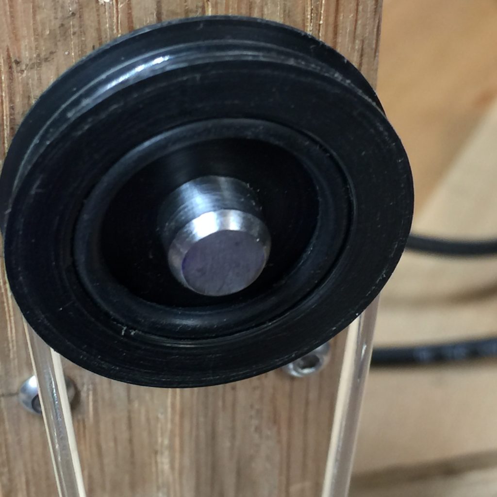
Pull-pin shaft with black rubber o-ring (above).
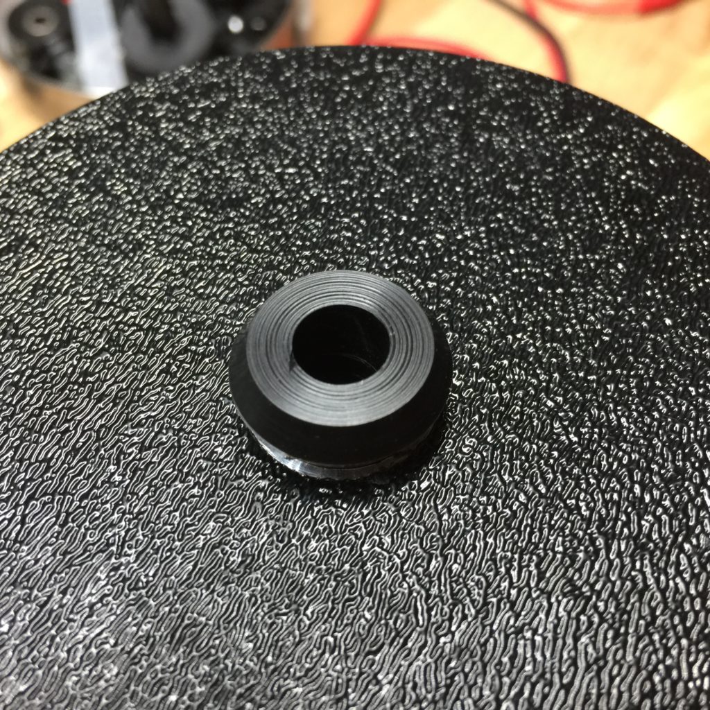
Bobbin with custom angled shaped hub that can fit within the o-ring pull-pin shaft even if slightly off axis (above).
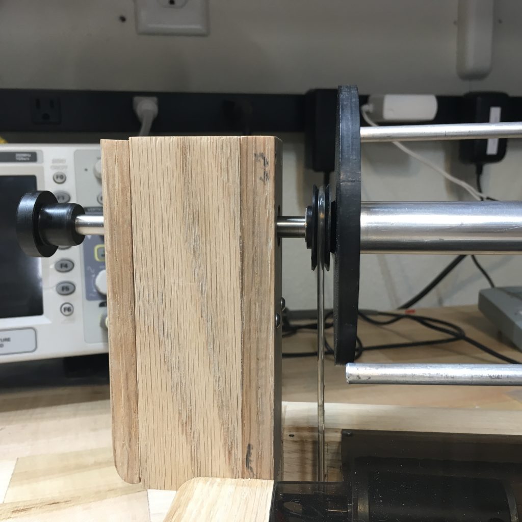
Close-up view of the pull-pin pulley with rubber o-ring making contact with the bobin’s angled hub (above). I call this solution a “clutch”.
Clutch defined:
“A clutch is a mechanical device which engages and disengages power transmission especially from driving shaft to driven shaft. In the simplest application, clutches connect and disconnect two rotating shafts (drive shafts or line shafts).”