Problem:
How to support the bobbin between the main front shaft and the rear pull-pin bobbin quick release shaft without using a flyer axel?
The main feature of the ewespinner is its ability to allow the quick removal and installation of the bobbin, without having to interact with drive/brake bands, whorls, pulleys, or the mechanism many spinning wheels require to allow the user to remove/install the bobbin.
For example, on spinning wheels that use the Scotch tension system, the bobbin spins on the flyer axle (steel round rod) connected to the main shaft. This flyer axle also supplies rotational forces to the bobbin by means of friction between itself and the bobbin’s two hubs (the round holes on each end of the bobbin). Basically, the flyer axle rotates via the main drive shaft (which is connected to the drive band), and do to friction between the flyer axle and the bobbin’s two hubs, the bobbin will then begin to rotate at the same rate as the flyer axle. It’s only when the user uses the Scotch tension band (the string wrapped around the bobbin’s pulley) that the bobbin will spin slower than the flyer (do to slippage). When the bobbin rotates slower than the flyer, the take-up is increased and any newly spun yarn starts to wind onto the bobbin.
The ewespinner doesn’t use the flyer axle design described above, instead, it uses the much improved and user friendly variable double-drive system. This system requires two motors: one for spinning the bobbin, and the other for spinning the flyer. Because there is no flyer axle to support the bobbin, the ewespinner requires two pivot points: one on the front vertical support post and one on the rear vertical support post. The front pivot point must spin freely with as little friction to the bobbin as possible and the rear pivot point provides rotation for the bobbin via a rubber o-ring clutch system.
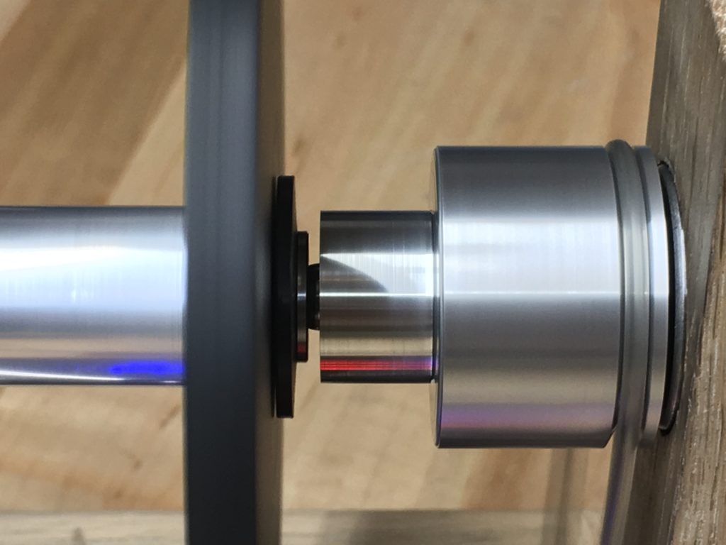
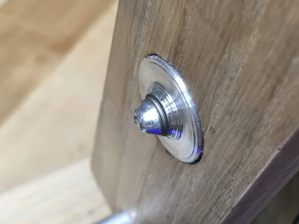
I have spent the last year coming up with different designs for both the front and rear pivot points. I recently solved the rear pivot point problem using a clutch design and I thought I had the front pivot design working. However, it turns out that the front pivot has an issue: where the aluminum pivot point mates with the bobbin’s steel bearing, the aluminum (which is a softer metal than steel) will wear down, causing the diameter of the pivot to be reduced slightly over time (see picture below). This reduction in diameter of the pivot results in the bearing having more room to move around, causing an annoying rattle. The design works, but the rattling sound makes the design a failure in my opinion.
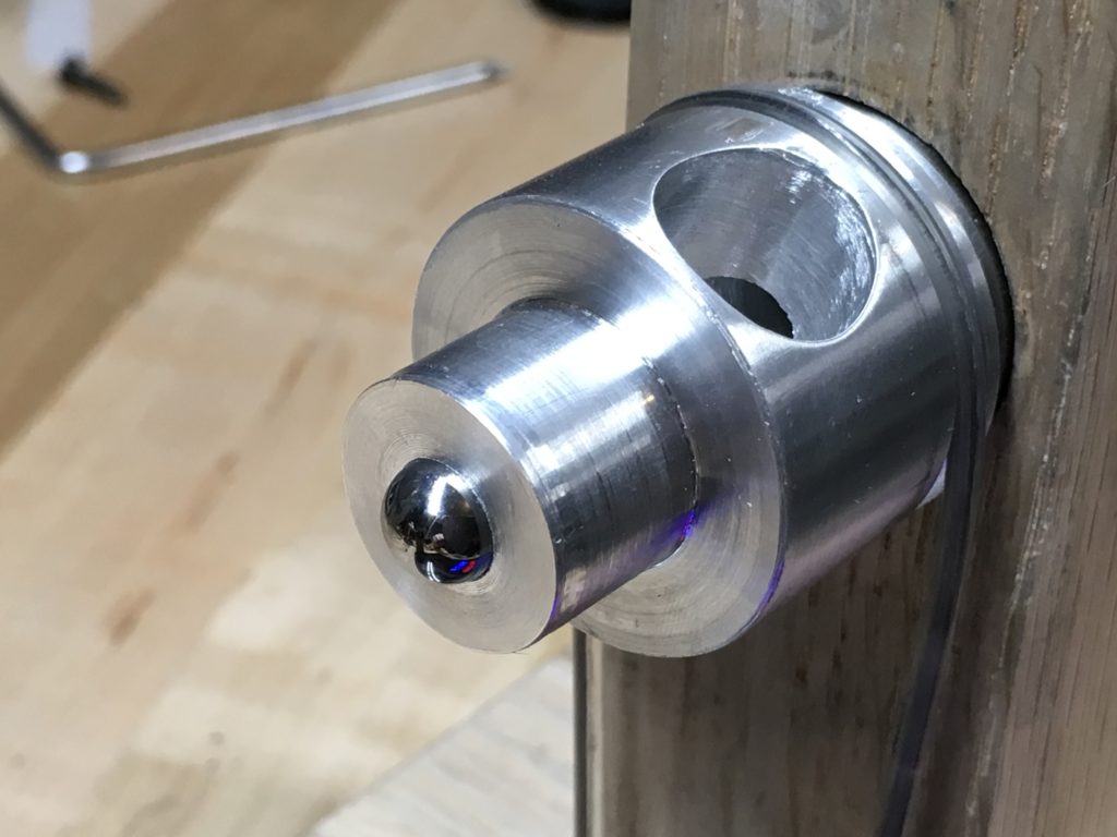
I am currently trying to come up with a new design that will resolve this rattling noise issue. I believe the solution is to use a material that is harder than aluminum. After much thought, instead of an aluminum pivot, I will drill a hole into the aluminum shaft and place a chrome steal ball into the hole (see picture below). Because the bobbin’s bearing and the pivot ball are both made of harden steel, the wear on the ball should be minimal, resulting in no rattle.
I will begin testing this new steel ball design in the coming weeks.